Unbricking: Difference between revisions
| (47 intermediate revisions by 2 users not shown) | |||
| Line 1: | Line 1: | ||
== Introduction == | == Introduction == | ||
If your radio bricked after you edited the config file, it is possible to unbrick it by removing the Barracuda module and placing it in a radio that has a different hardware-id e.g. a module from an Intempo (761), inside a Logik IR100 (1012). Once powered up, you can login and restore the config file edits (since the new radio boots using the config files for its radio hardware-id, not the one you messed up). | |||
The following procedure will take you through the restoration of your radio using a simple JTAG cable, with software we have provided. | |||
== Prerequisites == | == Prerequisites == | ||
| Line 7: | Line 9: | ||
In order to recover a bricked radio, you will need: | In order to recover a bricked radio, you will need: | ||
* JTAG | * JTAG hardware | ||
* Software for flashing over JTAG | * Software for flashing over JTAG | ||
* An image to flash to the radio | * An image to flash to the radio (see [[Making a backup]]) | ||
* A lot of patience | * A lot of patience | ||
== JTAG | == JTAG hardware == | ||
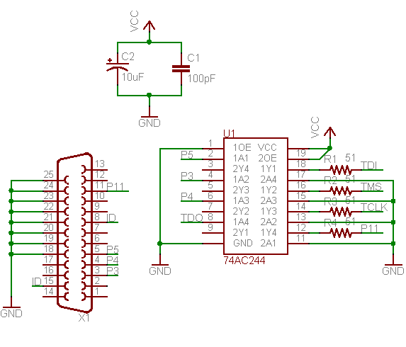
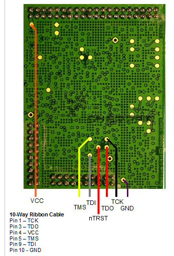
'Wiggler' compatible cables are a popular low-cost cable, and well supported by the free jtag tools. Plans to make your own are widely available, and prebuilt ones can be found cheaply on ebay and similar sites. A "universal" wiggler will come with bare wires which can be soldered to the [[Media:Barracuda-board-outline.jpg|jtag test points]] on the barracuda board. | 'Wiggler' compatible cables are a popular low-cost cable, and well supported by the free jtag tools. Plans to make your own are widely available, and prebuilt ones can be found cheaply on ebay and similar sites. | ||
A "universal" wiggler will come with bare wires which can be soldered to the [[Media:Barracuda-board-outline.jpg|jtag test points]] on the barracuda board. | |||
<table border=0><tr><td> | <table border=0><tr><td> | ||
| Line 22: | Line 26: | ||
</td></tr></table> | </td></tr></table> | ||
'''N.B. The Barracuda board needs to be installed in a powered up radio (standby is OK) for the JTAG process to work.''' | |||
Sharpflash supports only wigglers connected on the '''Parallel ports''' (LPT1, LPT2, LPT3) of your computer. Since these ports become very rare there may be the need to update Sarpflash to support wigglers on USB ports etc. | |||
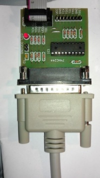
A cable and the JTAG unit that worked in a backup/restore test were: | |||
<table border=0><tr><td> | |||
[[Image:SharpfinWigglerExample.jpg|200px]] | |||
</td><td> | |||
[[Image:SharpflashCableExample.jpg|500px]] | |||
</td></tr></table> | |||
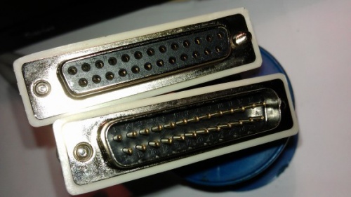
Note that the cable for this JTAG unit has both a male end (to be attached to the PC) and a female end that will be directly connected to the JTAG unit. The cable should NOT be too long (max 5m) and it should be a "normal" printer cable (DB-25), but '''not''' with 36 pins on the female end (like some very '''old''' printers had/have), but with the D-Sub (because it is D-shaped) 25pin on both sites (D-Sub M/F 25pin). | |||
The off-the-shelf unit should have the necessary bare wires to solder to the Reciva board. The only problem with those commercial wigglers is their usage of input pins. Hence, it may be necessary to adjust some of the inputs, e.g: | |||
[[Image:SharpflashWigglerBackside.jpg|200px]] | |||
=== Soldering === | |||
The bare cables of the JTAG unit must be soldered directly to the Reciva board on the JTAG interface. | |||
It seems that only Ground (GND) and the power supply (VCC) are available as pins on the board, for the rest we need to solder the bare cables directly to the gold-plated contact points. | |||
We need at least 4 of those (excluding also the nTrst point, that was not always needed in our tests). | |||
Hint: Put very little solder on the points of the Reciva board first, then a little bit on the bare wire and then connect them using a solder iron. This should not be too difficult and you do not need special soldering skills, just be sure to not damage the gold-plated contact points. An alternative that worked too is to build a transparent board (plastic, plexi) where you can plug in you bares, that you will place just above the Reciva board: | |||
<table border=0><tr><td> | |||
[[Image:SharpflashPinBoardOff.jpg|200px]] | |||
</td><td> | |||
[[Image:SharpflashPinBoardOn.jpg|500px]] | |||
</td></tr></table> | |||
But note that to construct the transparent board and fix the cables such that they are perfectly connected to the Reciva board may be even more difficult than solder the 4 + 2 wires to the board. | |||
Or see [http://recivarefuge.net/sharpfin/Barracuda%20connector.pdf Barracuda JTAG Connector]for instructions to make a custom connector which does not require soldering to the gold pads on the Reciva module. | |||
10/10/12 : [[User:Philipp]] used a off-the-shelf wiggler based on [[Media:wiggler2.png|this]] circuit that needed small modification (and soldering skills), see images above | |||
This | 19/08/08 : I used a wiggler based on [[Media:wiggler2.png|this]] circuit. This worked 100% on the first attempt. Note this uses HC rather than AC logic, which is advised in several places. | ||
== JTAG Flashing Software == | |||
The application sjf2410, along with the error correction code from the linux kernel have been modified to produce a bespoke utility for the baracuda module's NAND flash. It uses the wiggler cable in the parallel port. | |||
* [http://www.sharpfin.org/sharpfin/images/a/a4/Sharpflash_v0.4.zip Sharpflash v 0.4] - Source Code* ('''OLD:''' [http://www.sharpfin.org/sharpfin/images/c/c1/Sharpflash-src-0.1.tar.bz2 Sharpflash v 0.1 Alpha]) | |||
* [[Sharpflash Bugs]] | |||
* Sharpflash will be only provided as a source code snapshot (from github) since it is for more advanced users only which should be able to make/build the utility and adapt it | |||
=== Requirements === | |||
* Hardware | |||
** A parallel DB-25 female port | |||
** Reciva board (and the radio itself, we need to plug the board into the Radio's main board too to be able to run Sharpflash, after soldering the bare wires of the wiggler) | |||
** Cable (depending on your JTAG unit, LPT cable, DB-25 M/F 25 pin) | |||
** Solder iron | |||
* Software | |||
** Linux with root account OR Win 32bit w/ Cygwin and giveio.sys<sup>[[#foot_giveio|giveio]]</sup> installed (we could think of supporting also Inpout32.dll<sup>[[#foot_inpout32dll|inpout32]]</sup>) | |||
** Newest version of Sharpflash | |||
Sharpflash v 0.4 was successfully tested under Windows (Cygwin with ioperm and giveio) and under Ubuntu Linux (both running in a 32 bit environment). | |||
To use Sharpflash with a 64bit version of windows we may need Inpoutx64.dll<sup>[[#foot_inpoutx64dll|inpout64]]</sup>. | |||
This version of sharpflash supports reading and writing of the NAND flash using the wiggler parallel port interface. | |||
'''This software is far from perfect. It takes a lot of time to restore/backup the whole NAND flash''' | |||
=== Sharpflash Options === | |||
$ ./sharpflash.exe -h | |||
Sharpfin Flash Programmer. http://www.sharpfin.org/sharpfin/ | |||
sharpflash [-p 1|2|3] [-r|-w filename start length ] | |||
sharpflash [-p 1|2|3] [-b] | |||
-r -w Read flash to file, or write file to flash | |||
-b Check flash for bad blocks | |||
-p <n> n = 1, 2 or 3. Use LPT1 (default) LPT2 or LPT3 parallel port | |||
filename Destination / source filename, the file must be in nanddump format | |||
start Hex start address in NAND for read/write, must be a multiple of 0x4000 | |||
length Hex length to read/write. if file is too short, | |||
NAND will be filled with 0xFF. Must be a multiple of 0x4000 | |||
If no r,w or b argument is supplied, the program just tries to read the | |||
JTAG device ID of the flash and CPU using the configured parallel port, | |||
For r,w and b commands, the output data contains: | |||
w - page written OK | |||
r - page read OK | |||
. - page check OK | |||
b - page/block identified as bad | |||
B - page/block has just been marked bad | |||
v0.4, http://www.sharpfin.org/sharpfin/ | |||
=== Reading Flash Images === | |||
You can make a back-up of your flash via JTAG using the following format commands: | |||
sharpflash -r kernel-mtd.bin 004000 0fc000 | |||
Will extract the contents of the kernel partition into 'kernel-mtd1.bin', which is a ''nanddump'' format file, skipping any bad sectors as it goes. Have a look at [[Reciva NAND Flash]] for the background on the flash structure. | |||
== | Sharpfin Flash Programmer - http://www.sharpfin.org/sharpfin/ | ||
. | |||
Found S3C2410 processor on JTAG Cable | |||
Found K9F2808UOC on processor | |||
Reading NAND Flash: | |||
destination = kernel-mtd1.bin | |||
start addr = 0x4000 | |||
length = 0xFC000 | |||
. | |||
Address Progress Remaining | |||
------- -------------------------------- --------- | |||
0004000 rrrrrrrrrrrrrrrrrrrrrrrrrrrrrrrr 9h 12m | |||
0008000 rrrrrrrrrrrrrrrrrrrrrrrrrrrrrrrr 9h 11m | |||
000C000 rrrrrr | |||
=== Getting Bad Block Information === | |||
This is not needed for programming, however it is recommended that you keep a record of the bad blocks marked by the manufacturer as bad, because this information is stored in re-programmable memory, and it may be useful to be able to distinguish between manufacturer-defined bad blocks, and user-defined bad blocks. | |||
sharpflash -b | |||
The program will output several lines, with each '.' representing a 16K block which is marked as good, and a 'b' for each block which is marked bad. | |||
Sharpfin Flash Programmer - http://www.sharpfin.org/sharpfin/ | |||
. | |||
Found S3C2410 processor on JTAG Cable | |||
Found K9F2808UOC on processor | |||
Checking NAND Blocks | |||
0000000: ................................................................ | |||
0100000: bbbbbbbbbbbbbbbbbbbbbbbbbbbbbbbb............... | |||
=== | === Writing Flash Images === | ||
This process takes a long time to run - roughly 80 seconds per 16KBytes, so a full 16Mb flash will take about 24 hours. | |||
'''When you are choosing your images to write, make sure that they are in 'nanddump' format. Writing images to flash that are ''not'' in 'nanddump' format will result in valid blocks being marked bad''' | |||
sharpflash -w boot-mtd.bin 000000 04000 | |||
Will write the boot sector from the file boot-mtd.bin, and will produce an output similar to this: | |||
Sharpfin Flash Programmer - http://www.sharpfin.org/sharpfin/ | |||
. | |||
Found S3C2410 processor on JTAG Cable | |||
Found K9F2808UOC on processor | |||
Writing NAND Flash: | |||
source = boot-mtd.bin | |||
start addr = 0x0 | |||
length = 0x04000 | |||
. | |||
Address Progress Remaining | |||
------- -------------------------------- --------- | |||
0000000 wwwwwwwwwwwwwwwwwwwwwwwwwwwwwwww 0h 00m | |||
If you want to restore your whole radio nandumps, you may need all of the following commands: | |||
sudo ./sharpfin -w boot-mtd.bin 000000 004000 | |||
sudo ./sharpfin -w kernel-mtd.bin 004000 0FC000 | |||
sudo ./sharpfin -w root-mtd.bin 100000 D00000 | |||
sudo ./sharpfin -w config-mtd.bin E00000 100000 | |||
sudo ./sharpfin -w debug-mtd.bin F00000 100000 | |||
= | As above, the first number is the starting address and the second the nandump size (in hex). | ||
Please double-check if these sizes/addresses are correct for your radio too (e.g. via a working sharpfin webserver backup page or just try to get the numbers from the file-size and calculate the "next" address respectively). | |||
The formula of course is: | |||
new address = old address + old size | |||
(the order should always be boot, kernel, root, config, debug; but please double-check that too for your radio) | |||
= | = Interesting Information / Links = | ||
= | * [http://www.olimex.com/dev/arm-jtag.html Arm Programming Info] | ||
* [http://openocd.berlios.de/ OpenOCD Support for NAND flash via the S3C2410's built in controller] | |||
* [https://lists.berlios.de/pipermail/openocd-development/2007-March/000115.html patch supporting the K9F1208 Flash (similar to the K9F2808)] | |||
* [http://openwince.sourceforge.net/jtag/ OpenWinCE JTAG tools] | |||
* [http://jtager.cvs.sourceforge.net/jtager/jtager/doc/s3c2410.bsdl?view=log s3c2410.bsdl Support for OpenWinCE] | |||
* [http://jtager.sourceforge.net jtager] | |||
* [http://wiki.openmoko.org/wiki/Sjf2410-linux sjf2410 Used by the OpenMoko project] | |||
* [http://www.mizi.com/developer/s3c2410x/ jflash-s3c2410] | |||
* [http://www.freelabs.com/~whitis/electronics/jtag/ JTAG Information] | |||
* [http://www.ens-lyon.fr/LIP/Pub/Rapports/RR/RR2006/RR2006-08.pdf Arm/Linux Booting method] | |||
* [http://www.bioinspired.com/users/ajg112/electronics/parallelPort.shtml PC Parallel Port Access From Linux] | |||
* [http://www.ixo.de/info/usb_jtag/ JTAG USB Programming Info] | |||
* [http://www.ftdichip.com/Documents/ProgramGuides/FTCJTAGPG13.pdf FTDI Library, used by Altera ByteBlaster] | |||
* <span id="foot_inpoutx64dll">[http://logix4u.net/parallel-port/26-inpoutx64dll-for-win-xp-64-bit Windows IO port access on 64bit environment: inpoutx64.dll]</span> | |||
* <span id="foot_inpout32dll">[http://logix4u.net/component/content/article/14-parallel-port/16-inpout32dll-for-windows-982000ntxp Windows IO port access on 32bit environment: inpout32.dll]</span> | |||
* <span id="foot_giveio">[http://www.cs.ucr.edu/~eblock/pages/pictools/giveio.html Giveio.sys and Library Loader for Windows direct IO port access]</span> | |||
Latest revision as of 16:06, 19 January 2013
Introduction
If your radio bricked after you edited the config file, it is possible to unbrick it by removing the Barracuda module and placing it in a radio that has a different hardware-id e.g. a module from an Intempo (761), inside a Logik IR100 (1012). Once powered up, you can login and restore the config file edits (since the new radio boots using the config files for its radio hardware-id, not the one you messed up).
The following procedure will take you through the restoration of your radio using a simple JTAG cable, with software we have provided.
Prerequisites
In order to recover a bricked radio, you will need:
- JTAG hardware
- Software for flashing over JTAG
- An image to flash to the radio (see Making a backup)
- A lot of patience
JTAG hardware
'Wiggler' compatible cables are a popular low-cost cable, and well supported by the free jtag tools. Plans to make your own are widely available, and prebuilt ones can be found cheaply on ebay and similar sites.
A "universal" wiggler will come with bare wires which can be soldered to the jtag test points on the barracuda board.
N.B. The Barracuda board needs to be installed in a powered up radio (standby is OK) for the JTAG process to work.
Sharpflash supports only wigglers connected on the Parallel ports (LPT1, LPT2, LPT3) of your computer. Since these ports become very rare there may be the need to update Sarpflash to support wigglers on USB ports etc.
A cable and the JTAG unit that worked in a backup/restore test were:
Note that the cable for this JTAG unit has both a male end (to be attached to the PC) and a female end that will be directly connected to the JTAG unit. The cable should NOT be too long (max 5m) and it should be a "normal" printer cable (DB-25), but not with 36 pins on the female end (like some very old printers had/have), but with the D-Sub (because it is D-shaped) 25pin on both sites (D-Sub M/F 25pin).
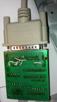
The off-the-shelf unit should have the necessary bare wires to solder to the Reciva board. The only problem with those commercial wigglers is their usage of input pins. Hence, it may be necessary to adjust some of the inputs, e.g:
Soldering
The bare cables of the JTAG unit must be soldered directly to the Reciva board on the JTAG interface. It seems that only Ground (GND) and the power supply (VCC) are available as pins on the board, for the rest we need to solder the bare cables directly to the gold-plated contact points.
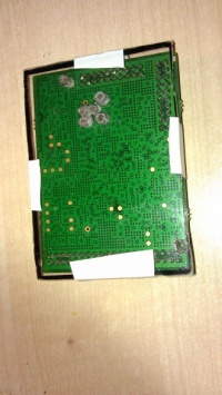
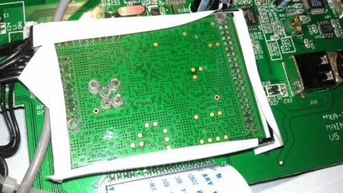
We need at least 4 of those (excluding also the nTrst point, that was not always needed in our tests). Hint: Put very little solder on the points of the Reciva board first, then a little bit on the bare wire and then connect them using a solder iron. This should not be too difficult and you do not need special soldering skills, just be sure to not damage the gold-plated contact points. An alternative that worked too is to build a transparent board (plastic, plexi) where you can plug in you bares, that you will place just above the Reciva board:
But note that to construct the transparent board and fix the cables such that they are perfectly connected to the Reciva board may be even more difficult than solder the 4 + 2 wires to the board.
Or see Barracuda JTAG Connectorfor instructions to make a custom connector which does not require soldering to the gold pads on the Reciva module.
10/10/12 : User:Philipp used a off-the-shelf wiggler based on this circuit that needed small modification (and soldering skills), see images above
19/08/08 : I used a wiggler based on this circuit. This worked 100% on the first attempt. Note this uses HC rather than AC logic, which is advised in several places.
JTAG Flashing Software
The application sjf2410, along with the error correction code from the linux kernel have been modified to produce a bespoke utility for the baracuda module's NAND flash. It uses the wiggler cable in the parallel port.
- Sharpflash v 0.4 - Source Code* (OLD: Sharpflash v 0.1 Alpha)
- Sharpflash Bugs
* Sharpflash will be only provided as a source code snapshot (from github) since it is for more advanced users only which should be able to make/build the utility and adapt it
Requirements
- Hardware
- A parallel DB-25 female port
- Reciva board (and the radio itself, we need to plug the board into the Radio's main board too to be able to run Sharpflash, after soldering the bare wires of the wiggler)
- Cable (depending on your JTAG unit, LPT cable, DB-25 M/F 25 pin)
- Solder iron
- Software
Sharpflash v 0.4 was successfully tested under Windows (Cygwin with ioperm and giveio) and under Ubuntu Linux (both running in a 32 bit environment). To use Sharpflash with a 64bit version of windows we may need Inpoutx64.dllinpout64.
This version of sharpflash supports reading and writing of the NAND flash using the wiggler parallel port interface.
This software is far from perfect. It takes a lot of time to restore/backup the whole NAND flash
Sharpflash Options
 $ ./sharpflash.exe -h

 Sharpfin Flash Programmer. http://www.sharpfin.org/sharpfin/


 sharpflash [-p 1|2|3] [-r|-w filename start length ]
 sharpflash [-p 1|2|3] [-b]

   -r -w      Read flash to file, or write file to flash
   -b         Check flash for bad blocks
   -p <n>     n = 1, 2 or 3. Use LPT1 (default) LPT2 or LPT3 parallel port
   filename   Destination / source filename, the file must be in nanddump format
   start      Hex start address in NAND for read/write, must be a multiple of 0x4000
   length     Hex length to read/write. if file is too short,
              NAND will be filled with 0xFF. Must be a multiple of 0x4000

 If no r,w or b argument is supplied, the program just tries to read the
 JTAG device ID of the flash and CPU using the configured parallel port,

 For r,w and b commands, the output data contains:

    w - page written OK
    r - page read OK
    . - page check OK
    b - page/block identified as bad
    B - page/block has just been marked bad

 v0.4, http://www.sharpfin.org/sharpfin/
Reading Flash Images
You can make a back-up of your flash via JTAG using the following format commands:
sharpflash -r kernel-mtd.bin 004000 0fc000
Will extract the contents of the kernel partition into 'kernel-mtd1.bin', which is a nanddump format file, skipping any bad sectors as it goes. Have a look at Reciva NAND Flash for the background on the flash structure.
Sharpfin Flash Programmer - http://www.sharpfin.org/sharpfin/
.
Found S3C2410 processor on JTAG Cable
Found K9F2808UOC on processor
Reading NAND Flash:
 destination   = kernel-mtd1.bin
 start addr    = 0x4000
 length        = 0xFC000
.
Address  Progress                          Remaining
-------  --------------------------------  ---------
0004000  rrrrrrrrrrrrrrrrrrrrrrrrrrrrrrrr    9h 12m
0008000  rrrrrrrrrrrrrrrrrrrrrrrrrrrrrrrr    9h 11m
000C000  rrrrrr
Getting Bad Block Information
This is not needed for programming, however it is recommended that you keep a record of the bad blocks marked by the manufacturer as bad, because this information is stored in re-programmable memory, and it may be useful to be able to distinguish between manufacturer-defined bad blocks, and user-defined bad blocks.
sharpflash -b
The program will output several lines, with each '.' representing a 16K block which is marked as good, and a 'b' for each block which is marked bad.
Sharpfin Flash Programmer - http://www.sharpfin.org/sharpfin/
.
Found S3C2410 processor on JTAG Cable
Found K9F2808UOC on processor
Checking NAND Blocks
 0000000: ................................................................
 0100000: bbbbbbbbbbbbbbbbbbbbbbbbbbbbbbbb...............
Writing Flash Images
This process takes a long time to run - roughly 80 seconds per 16KBytes, so a full 16Mb flash will take about 24 hours.
When you are choosing your images to write, make sure that they are in 'nanddump' format. Writing images to flash that are not in 'nanddump' format will result in valid blocks being marked bad
sharpflash -w boot-mtd.bin 000000 04000
Will write the boot sector from the file boot-mtd.bin, and will produce an output similar to this:
Sharpfin Flash Programmer - http://www.sharpfin.org/sharpfin/
.
Found S3C2410 processor on JTAG Cable
Found K9F2808UOC on processor
Writing NAND Flash:
 source      = boot-mtd.bin
 start addr  = 0x0
 length      = 0x04000
.
Address  Progress                          Remaining
-------  --------------------------------  ---------
0000000  wwwwwwwwwwwwwwwwwwwwwwwwwwwwwwww    0h 00m
If you want to restore your whole radio nandumps, you may need all of the following commands:
 sudo ./sharpfin -w boot-mtd.bin   000000 004000
 sudo ./sharpfin -w kernel-mtd.bin 004000 0FC000
 sudo ./sharpfin -w root-mtd.bin   100000 D00000
 sudo ./sharpfin -w config-mtd.bin E00000 100000
 sudo ./sharpfin -w debug-mtd.bin  F00000 100000
As above, the first number is the starting address and the second the nandump size (in hex). Please double-check if these sizes/addresses are correct for your radio too (e.g. via a working sharpfin webserver backup page or just try to get the numbers from the file-size and calculate the "next" address respectively). The formula of course is: new address = old address + old size (the order should always be boot, kernel, root, config, debug; but please double-check that too for your radio)
Interesting Information / Links
- Arm Programming Info
- OpenOCD Support for NAND flash via the S3C2410's built in controller
- patch supporting the K9F1208 Flash (similar to the K9F2808)
- OpenWinCE JTAG tools
- s3c2410.bsdl Support for OpenWinCE
- jtager
- sjf2410 Used by the OpenMoko project
- jflash-s3c2410
- JTAG Information
- Arm/Linux Booting method
- PC Parallel Port Access From Linux
- JTAG USB Programming Info
- FTDI Library, used by Altera ByteBlaster
- Windows IO port access on 64bit environment: inpoutx64.dll
- Windows IO port access on 32bit environment: inpout32.dll
- Giveio.sys and Library Loader for Windows direct IO port access
