Probe Pins: Difference between revisions
Jump to navigation
Jump to search
No edit summary |
No edit summary |
||
| Line 1: | Line 1: | ||
There are a number of unidentified probe pins on the rear of the Reciva PCB. | There are a number of unidentified probe pins on the rear of the Reciva PCB. | ||
The following plots have been captured, monitoring these pins: | The following plots have been captured, monitoring these pins: | ||
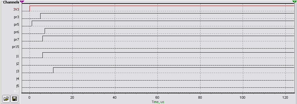
Note that the 3V3 is the 3V3 rail on the 'motherboard'. PR3 is the 3V3 rail on the barracuda module. Note that PR5 comes up before PR3, which suggests it is an input to the module. | |||
Probe Pins j1, j2, j3, j4, j5, PR3, PR5, PR6, PR7 and PR15 during power-up are shown in the image below. It should be noted that there is no further activity on these pins. | Probe Pins j1, j2, j3, j4, j5, PR3, PR5, PR6, PR7 and PR15 during power-up are shown in the image below. It should be noted that there is no further activity on these pins. | ||
[[Image:Power-up-plot.png]] | [[Image:Power-up-plot.png]] | ||
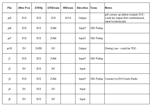
Voltage measurements have been made: | |||
[[Image:pin-diag-voltages.png]] | |||
Revision as of 16:50, 6 January 2007
There are a number of unidentified probe pins on the rear of the Reciva PCB. The following plots have been captured, monitoring these pins:
Note that the 3V3 is the 3V3 rail on the 'motherboard'. PR3 is the 3V3 rail on the barracuda module. Note that PR5 comes up before PR3, which suggests it is an input to the module.
Probe Pins j1, j2, j3, j4, j5, PR3, PR5, PR6, PR7 and PR15 during power-up are shown in the image below. It should be noted that there is no further activity on these pins.
Voltage measurements have been made:

