Probe Pins: Difference between revisions
Jump to navigation
Jump to search
No edit summary |
No edit summary |
||
| Line 2: | Line 2: | ||
The following plots have been captured, monitoring these pins: | The following plots have been captured, monitoring these pins: | ||
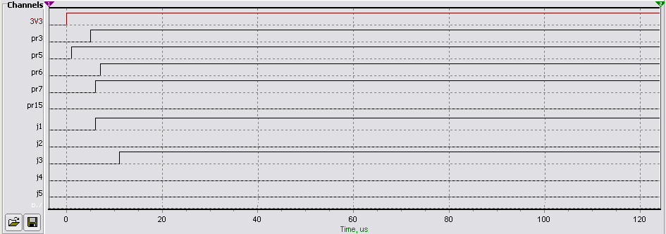
Probe Pins PR5, PR6, PR7 and PR15 during power-up | Probe Pins j1, j2, j3, j4, j5, PR3, PR5, PR6, PR7 and PR15 during power-up are shown in the image below. It should be noted that there is no further activity on these pins. | ||
[[Image:Power-up-plot.png]] | [[Image:Power-up-plot.png]] | ||
Revision as of 16:05, 6 January 2007
There are a number of unidentified probe pins on the rear of the Reciva PCB. The following plots have been captured, monitoring these pins:
Probe Pins j1, j2, j3, j4, j5, PR3, PR5, PR6, PR7 and PR15 during power-up are shown in the image below. It should be noted that there is no further activity on these pins.
